Electronic Circuits - interfacing with a Z80 microprocessor v3 (data and address buses)
My seb80 custom computer now has its own page here
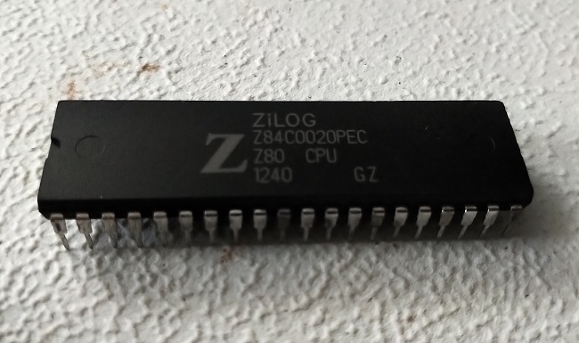
This is version 3 of my Z80 interfacing project. My goal here was to begin building the data and address buses.
Previous versions:
Previous versions:
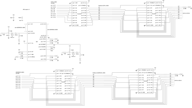
My time on version 3 was split into three equal parts: first, research a unidirectional buffer for the address bus and a bidirectional buffer for the data bus. To this end, I've used 74LS244 and 74LS245, respectively. Second, start building these connections on the breadboard, along with some LEDs for the data bus. Third, create a diagram on the computer to replace the one in my notebook.
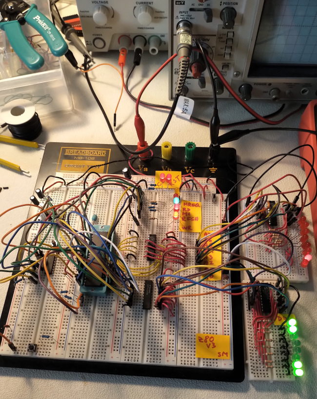
In the image above, you can see the green data bus LEDs. The red LEDs are tied to the address lines A0-A7, through their own 74LS244 buffer (just like the green ones).
The two small breadboards can be considered as external devices, each connected to a CPU bus.
Log
day 1Wired up a 74LS244 to test out logic levels (high and low level voltages) with and without loads.
I had a VERY bad time with a few 22 Ohm resistors that accidentally fell into the 1k Ohm resistor compartment.
Thankfully, the 74LS244 seems ok even after momentarily drawing 40mA more than when unloaded from one output pin with the wrong resistor.
My 74LS244 is actually a Signetics S74LS244N.
From a 5V supply, its unloaded high voltage is 3.7V. Drawing 3mA drops that to 3.4V. Drawing 6mA drops it to 3.35V. Drawing 12mA drops it to 3V, still above the TTL high level output low bound of 2.7V.
Hooked up a 74LS244 to stand in for the buffer for the lower 8 address bits (A0-A7).
day 2
Started planning the breadboard layout to bring in a unidirectional buffer for A0-A7 and a bidirectional one (transceiver) for D0-D7.
Bought a few breadboard segments because I was running out of space.
day 3
Wired up a 74LS245 (actual model is DM74LS245N) to data lines D0-D7.
As soon as I did that, my power supply shot up to the (rather conservative) current limit of 120mA.
I shut it down immediately and started looking for a short-circuit, or maybe a wrong direction in the 74LS245 (it's all hardwired for now).
I measured the supply current of the 74LS245 and was very surprised to see that it drew 47mA!
I even checked a few different types of 74LS245 and found typical supply current draw specified between 40mA and 90mA.
Now that I think about it, it is about double what the octal buffer 74LS244 draws, which has half the amount of Schmitt Triggers (8 instead of 16).
My DM74LS245N outputs a good high-level voltage of 3.7V (when supplied with 5V).
day 4
Started drawing up digitally everything I built so far.
day 5
More work on the diagram. I'm also building some small templates to make modifications to the diagram easier.
day 6
More work on the diagram. It has many lines now.
day 7
Wired up indicator LEDs to the data bus as well. They are treated like any other device connected to that bus in that they're behind their own buffer. This minimizes the risk of voltage dropping outside of TTL levels when more devices will be connected to the data bus.
Diagrams
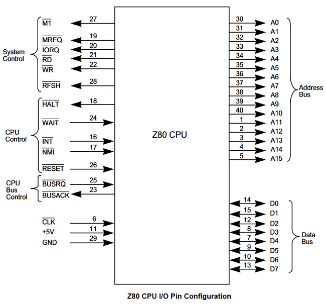
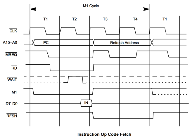
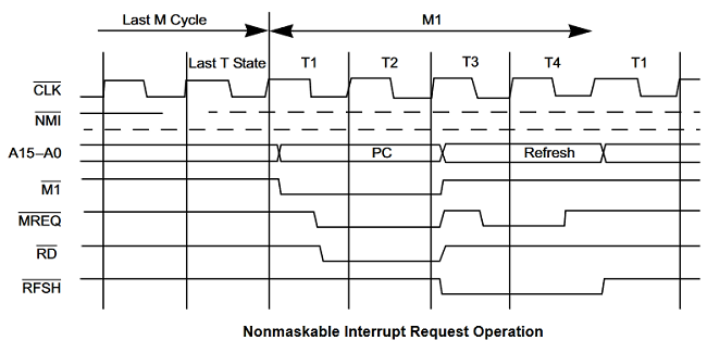
Here are some useful diagrams, including the Z80 pinout, timing diagrams, etc.