Electronic Circuits - interfacing with a Z80 microprocessor v2 (observe machine cycles)
My seb80 custom computer now has its own page here
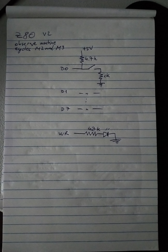
This is version 2 of my Z80 interfacing project. My goal here was to observe machine cycles M2 and M3 (memory read and memory write, respectively), while changing the values on the data lines via DIP switches.
Previous versions:
version 1 - initial wire-up, executes NOPs, observe incrementing address
Previous versions:
version 1 - initial wire-up, executes NOPs, observe incrementing address
One difficulty I encountered here was that I had a faulty chip. This caused many hours of frustration and debugging, thinking that my setup was causing the issue. See log for more information.
The current-limiting power supply came in handy. With only pull-up resistors near the DIP switches, as soon as the CPU enabled its data lines (for writing), they short-circuited to ground. I shut off the power quickly enough to avoid damage. I followed up immediately with resistors near ground to avoid this.
Log
day 1Hooked up DIP switches to control data lines.
CPU enters a bad state AFTER successfully executing any instruction which reads an operand from memory (e.g.: JP nn).
NOP still works well; I can execute many of them sequentially.
day 2
I've tried with a more complex instruction, JP nn. This should branch unconditionally to the address in nn (2-byte). This would becomes observable on the address lines as soon as JP nn finishes executing.
For some reason, only the first JP nn executes successfully. ANY other instruction that comes after fails (e.g.: NOP, JP nn, etc.)
day 3
Traced and recorded all outputs after the successful first instruction.
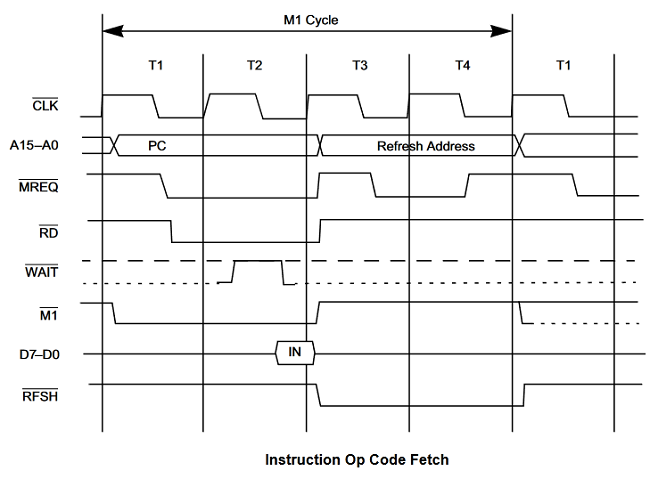
It looks like the CPU goes into a bad state and never finishes the M1 (opcode fetch machine cycle) of the second instruction.
If I wired something up incorrectly, I'm surprised JP nn's M2 (memory read) cycles complete successfully.
Changed some resistors, removed some components to try to eliminate the source of failure, without success.
What makes this strange is that the first instruction is always successful, and the second always fails.
day 4
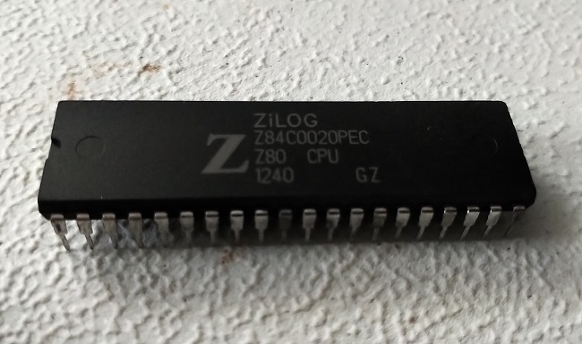
Tried a different Z80 CPU and concluded that the first one was faulty.
The good CPU not only draws significantly less current, but also shows high-level voltages that are closer to 5V on its output pins.
day 5
Tested a few more instructions, including ones that write to the data lines.
Since I don't yet have a proper bus built, I added resistors at ground (series with switches), along with the pull up resistors, to ensure no short circuits happen when the CPU enables its data pins (low impedance, "write" mode).
When reading from "memory" - that is, my switches - CPU pins are high impedance ("read" mode), so that's not an issue in that case.

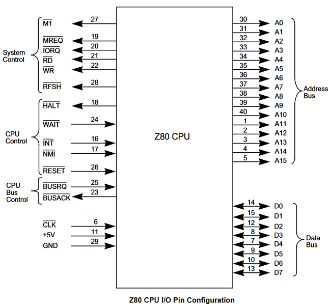
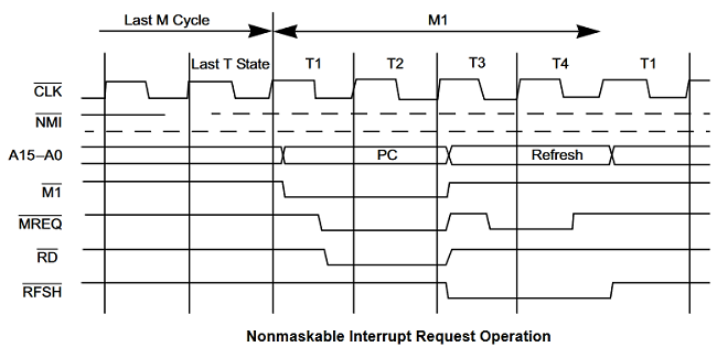
Diagrams
Here are some useful diagrams, including the Z80 pinout, timing diagrams, etc.