Electronic circuits - Catch That LED!

Catch That LED! is a simple electronic game which tests the player's reflexes. The player flips a switch to "catch" the green LED in the middle.
I designed Catch That LED! a few years ago; however, since I've only recently begun soldering, creating the game on a board seemed like a good way to advance my soldering skills.
Notable changes from the original design are the addition of a RC debouncer for the player input switch and the replacement of an IC with a single transistor.
Day-by-day progress photos
Here are some of the stages of the circuit being produced:
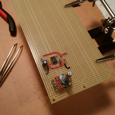 I began by setting up the first 555 timer, whose signal (astable) is used to advance the currently-lit LED.
The potentiometer varies the frequency.
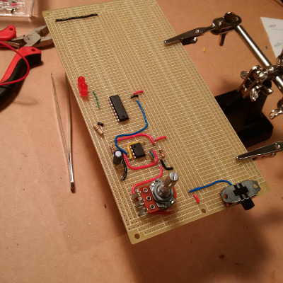 Work began on the counter IC, whose job is to iterate through the ten LEDs.
The player's switch has also been added here.
 The LEDs are now properly aligned and soldered in their slots.
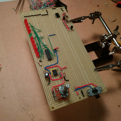 All LEDs have been wired up here.
Also, the audio pitch modifier has been added. Its purpose is to change the frequency of the sound being played by changing the speaker's 555 timer's RC time constant.
 The speaker's 555 timer (astable) is now fully connected.
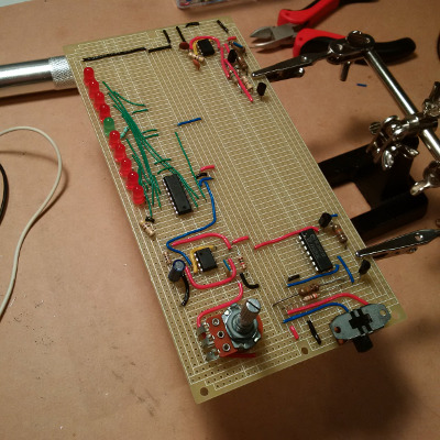 The next step was to add the logic checks which determine whether the speaker outputs a high-pitched "you won!" sound, or stops altogether for the "you lost!" case.
 Next, the logic checks which make the speaker alternate between two different sound frequencies as the LEDs are "running".
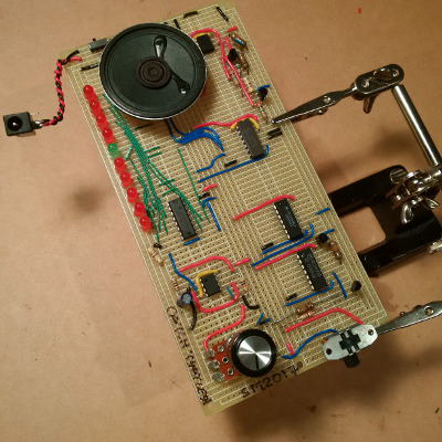 Finally, the speaker was mounted to the board and connected; the potentiometer received its knob.
A power plug along with an on/off switch were also added near the speaker.
The player input debouncer (RC circuit) was also added here.
 So far, this is the best soldering job I've done.