Catch That LED! - an electronic game circuit
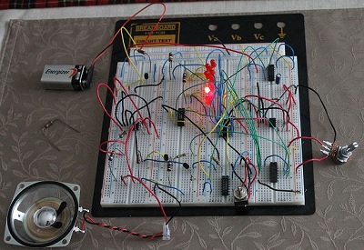
It was awesome when I got a standard 555 circuit to work and flash a LED. Soon after, I replaced the LED with a speaker. Then I thought - I can now do sound, LEDs can be a decent UI, and buttons can be inputs; I can make a game! Some of the inspiration came from a win-real-prizes type machine I saw at the movie theatre. In Catch That LED!, you are testing your reflexes and sense of timing by trying to "catch" the green LED. A high-pitched sound indicates success.
The difficulty can be adjusted via the potentiometer. Higher difficulty means faster LEDs, and therefore harder to catch.
As an additional mode, the circuit can be used as a flashy random number generator (generating one out of ten numbers), by reducing the resistance in the LED timer as well as using a smaller capacitor. The result is that the output frequency of the 555 chip will increase, so the LEDs will appear to all be on at once, and when the switch is activated, only one LED will remain on, "randomly".
Circuit details
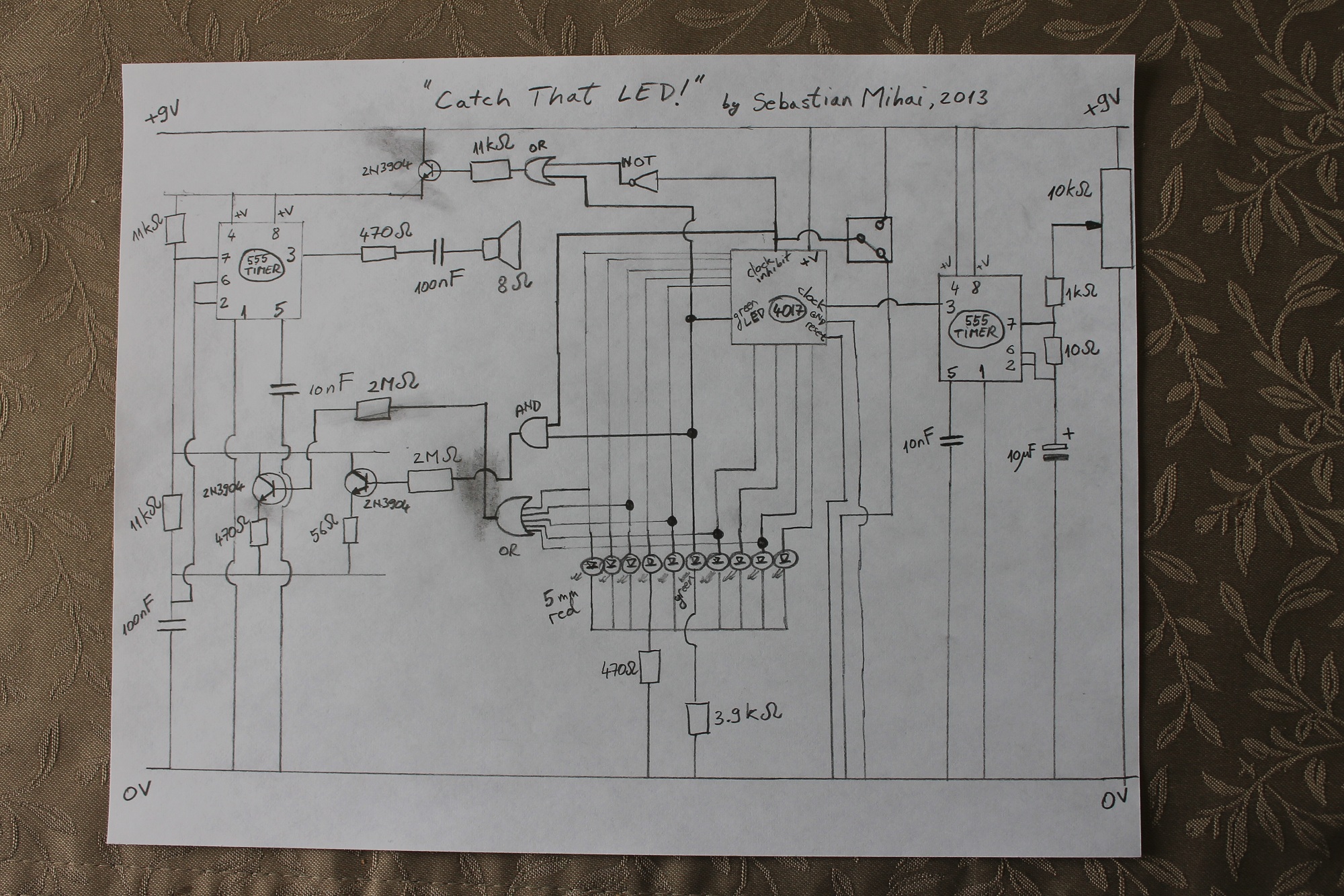
The circuit is made up of the following parts:
A. Sound component - It is based on a 555 timer in astable mode, connected to a speaker. It outputs continuously, unless the player activated the input switch at the wrong time (see component F below). The frequency is modified by resistors connected in parallel, and through transistors. This allows for different sounds to play. There are two sounds being played alternatingly as the LEDs turn on and off, and a third sound for when the player wins.
Notable is the capacitor connected in series with the speaker, which is meant to allow only alternating current through, so that the speaker is driven properly.
B. LED timing component - It is also based on a 555 timer in astable mode. Its output is much lower frequency than the sound 555 chip so that there's a visible delay between the LEDs turning on and off. There is a potentiometer connected in series with the other two resistors, which controls the difficulty of the game.
C. The LED component - It uses the output from the LED timer input into a decade counter chip. Each of the counter's ten pins goes high and then low, sequentially, turning on and off each LED. Every other LED also inputs into an OR gate. This determines when the second sound is played, as the output of the OR gate is input into the base of a transistor. When this happens, a resistor is connected in parallel with a static resistor which determines the sound frequency. The effect is that every other LED, the sound will be higher in frequency, as the resistance in the sound component is decreased.
D. Player input component - It is based on a SPDT switch connected to the "clock inhibit" pin on the decade counter. When the switch is in the default position, the pin is grounded, so the counter operates normally. When the player switches to the on position, the pin is connected to +9V. This causes pulses on the clock pin to be ignored, essentially freezing the counter. Whatever counter output pin was high at the time will be kept high, keeping the respective LED on.
E. Win detection component - It is done via an AND gate which ANDs together the value at the "clock inhibit" pin and the green LED. The output of the AND operation is input into a transistor, which adds a low resistance in parallel to the resistance which controls the frequency of the sound component. The effect is significantly lower resistance in the sound generator, resulting in a higher-pitched sound, indicating a win.
In logic notation,
p = the player activated the input switch
q = the green LED is on
Therefore, Win = p AND q
F. Sound stopping component - If the player activates the input switch at the wrong time (as in, the green LED is not lit), a transistor will open the sound component, so that no sound will play. At all other times, the sound is playing.
Here's the table of truth for this scenario; a "1" in the output means sound is playing.
Using
p = the player activated the input switch
q = the green LED is on
like above, then
p q output
0 0 1
0 1 1
1 0 0
1 1 1
Notice that the output is simply p -> q (IF p THEN q), which can be reduced as such:
SoundPlaying = p -> q = q OR (NOT p)