Capacitor study circuit
As I am slowly learning about electronics and electricity, I wanted to share the circuit I made to help me study capacitors, as well as experiment with voltage dividers (the potentiometer) and LEDs.
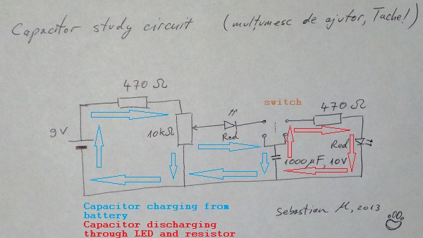
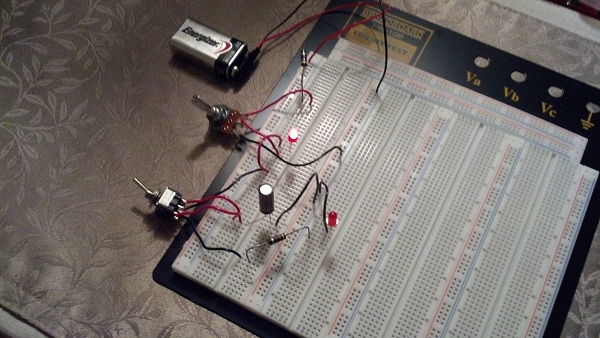
The circuit operates in two modes: charging and discharging. When the switch is connected to the "left" side of the circuit, current flows as indicated by the blue arrows, charging the capacitor from the battery. The time taken to charge is dictated by the variable resistor. Higher resistance means longer charging times. In the picture below, the LED closest to the battery slowly fades as the capacitor charges, and current decreases.
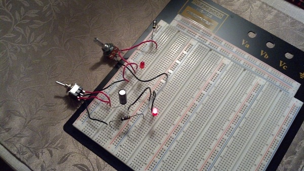
Once the switch is connected to the "right" side of the circuit, the capacitor is discharging and generating current as shown by the red arrows. While discharging, we can disconnect the battery completely, as shown below. The other (closest to capacitor) LED now fades, as the capacitor discharges, because of the decreasing current.
Measuring around with a multimeter will show the variations in current and voltage in various places. A word of caution: ensure your potentiometer is properly connected, or you risk a small fire with a lot of smoke. I remember reading somewhere that at some point everyone will have smoke coming out of a part. At the time I scoffed overconfidently, but was soon proven wrong by a mis-connected potentiometer.
The circuit operates in two modes: charging and discharging. When the switch is connected to the "left" side of the circuit, current flows as indicated by the blue arrows, charging the capacitor from the battery. The time taken to charge is dictated by the variable resistor. Higher resistance means longer charging times. In the picture below, the LED closest to the battery slowly fades as the capacitor charges, and current decreases.
Once the switch is connected to the "right" side of the circuit, the capacitor is discharging and generating current as shown by the red arrows. While discharging, we can disconnect the battery completely, as shown below. The other (closest to capacitor) LED now fades, as the capacitor discharges, because of the decreasing current.
Measuring around with a multimeter will show the variations in current and voltage in various places. A word of caution: ensure your potentiometer is properly connected, or you risk a small fire with a lot of smoke. I remember reading somewhere that at some point everyone will have smoke coming out of a part. At the time I scoffed overconfidently, but was soon proven wrong by a mis-connected potentiometer.