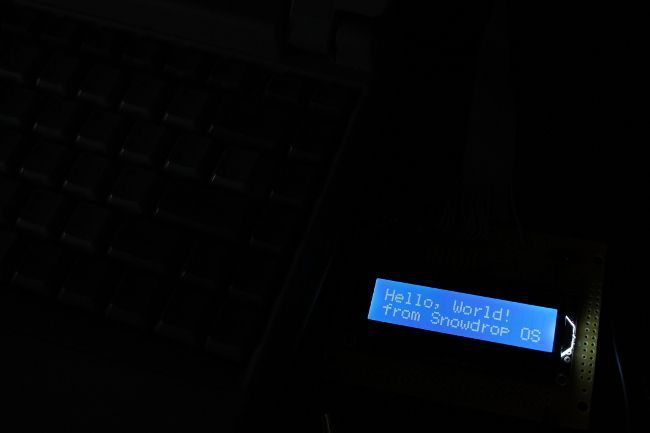
Electronic circuits - interfacing with a 16x2 LCD via parallel port
On the hardware side, the LCD1602 module is connected more or less directly to the PC parallel port. A capacitor was added in parallel to the ENABLE pin to help with electromagnetic interference (EMI) caused by changes in current when pins change values.
The parallel port is a great alternative to micro-controllers or single-board computers like Arduino and Raspberry Pi.
On the software side, I wrote the controller program as a Snowdrop OS app, in assembly language. For the source code, please see the Snowdrop OS pages. The source code also contains connection diagrams.


 I first built a breadboard prototype, with switches as inputs.
Here, you can see the typical current drawn by the LCD1602 module (this one is OSEPP brand): 1.2mA.
This does NOT include the backlight, which draws significantly more than that.
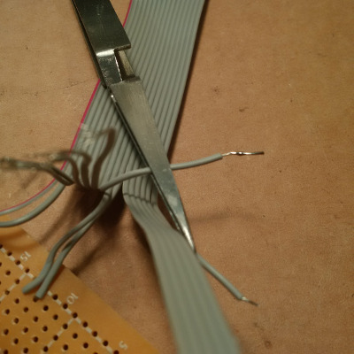 To make soldering stranded wire to the PCB easier, I first coated the ends in solder, essentially making the wire solid.
 Electromagnetic interference (EMI) caused by data pins changing between high and low caused pulses on the ENABLE pin, writing extra, undesirable characters to the LCD.
All the garbage "P" characters displayed here were due to EMI pulses on the ENABLE pin.